Table of Contents (17)
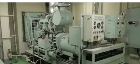
Emergency generators serve as one of the most critical life-safety installations aboard merchant vessels. Their duty is straightforward yet paramount: to maintain the continuity of essential navigation, communication, and safety systems when the vessel suffers a complete failure of the main electrical power plant (blackout).
A ship in blackout at sea loses propulsion, steering, and main lighting. Without an operational emergency power source, navigational aids such as radar and ECDIS go dark, radio communications cease, and electrically driven firefighting and bilge pumping apparatus become inoperative.
This comprehensive operational and regulatory guide details the requirements set forth by the International Convention for the Safety of Life at Sea (SOLAS), outlines practical testing procedures used by sea-going marine engineers, and analyzes common Port State Control (PSC) audit deficiencies.
Governing SOLAS Regulations
Emergency electrical power generation and distribution aboard commercial vessels are strictly regulated under the following key conventions:
- SOLAS Chapter II-1, Regulation 42: Emergency source of electrical power in passenger ships.
- SOLAS Chapter II-1, Regulation 43: Emergency source of electrical power in cargo ships.
- SOLAS Chapter II-1, Regulation 44: Starting arrangements for emergency generating sets.
- SOLAS Chapter II-2, Regulation 4.2.1: Fire safety and fuel oil flashpoint limitations.
1. Purpose and Operational Role of the Emergency Generator
The primary function of the emergency generator is to provide dependable auxiliary electrical power to designated safety, navigation, and emergency equipment in the event of a blackout.
Key services supplied by the emergency generating plant include:
- Navigation and Bridge Systems: Radar systems, Gyrocompass, ECDIS, and GPS receivers.
- Emergency Lighting: Illumination along all escape routes, muster stations, boat decks, alleyways, machinery control rooms, steering gear compartments, and the navigation bridge.
- Fire Safety Installations: Fire detection and general alarm panels, fixed fire-extinguishing controls, and emergency fire pumps (where electrically powered).
- External and Internal Communications: GMDSS radio consoles, handheld marine VHF chargers, public address (PA) systems, and navigation bridge telegraphs.
- Vessel Maneuverability & Water Ingress: Steering gear power units (as specified by vessel size and class rules) and emergency bilge suction pumps.
2. SOLAS Location Requirements (Chapter II-1, Reg. 42 & 43)
To safeguard the emergency power plant against casualties occurring in the main machinery rooms (such as engine room fires or catastrophic flooding), SOLAS imposes stringent location criteria:
- Outside Machinery Spaces of Category A: The emergency generator room must be situated completely outside the boundaries of Category A machinery spaces.
- Above the Uppermost Continuous Deck: The installation must be located above the uppermost continuous deck and outside the collision bulkhead (aft of the forward collision bulkhead).
- Open Deck Access: The compartment must have direct access from the open deck, enabling shipboard personnel to reach the space safely even if internal accommodation stairways or engine spaces are filled with smoke or heat.
- Fire-Rated Structural Boundaries: Bulkheads and decks separating the emergency generator room from Category A spaces, galleys, or control stations must meet A-60 fire insulation standards.
- Operating Inclination Limits: Under SOLAS II-1 Reg 42.1.3 & 43.1.3, the engine and electrical equipment must be designed and certified to operate continuously with the vessel listed up to 22.5° (athwartships) and trimmed up to 10° (fore-and-aft), or any dynamic combination thereof.
3. Automatic Starting Requirements (SOLAS Ch. II-1, Reg. 44)
In an emergency, every second counts. SOLAS sets precise operational parameters for automatic starting and starting medium redundancy:
45-Second Auto-Start and Load Transfer
Upon loss of the main electrical power supply, the emergency generating set must:
- Automatically start upon detection of main voltage loss.
- Accelerate to rated speed and achieve nominal voltage and frequency.
- Automatically connect to the Emergency Switchboard (ESB) and assume emergency loads within a maximum elapsed time of 45 seconds.
Redundant Starting Systems
Regulation 44 requires the emergency generator set to be fitted with two independent starting systems:
| Starting System | Energy Source | Minimum Capacity Required |
|---|---|---|
| Primary System | Electric battery starting system | Minimum of 3 consecutive starts |
| Secondary System | Hydraulic starter, pneumatic air receiver, or secondary battery set | Additional 3 starts within 30 minutes (or manual mechanical crank if demonstrated effective) |
Ambient Temperature Capability
Under SOLAS II-1 Regulation 44.1, starting arrangements must be certified to start the cold engine at an ambient temperature of 0°C. For vessels operating regularly in polar or freezing climates, thermostatically controlled cooling water jacket heaters, sump oil heaters, or space heaters must be installed and continuously monitored.
4. Fuel Storage and System Independence
The emergency generator diesel engine relies on a completely independent fuel oil supply system:
- Dedicated Fuel Tank: The fuel must be stored in a dedicated day tank located inside or adjacent to the emergency generator compartment, entirely isolated from main engine fuel systems.
- Minimum Operational Duration:
- Cargo Vessels: Fuel capacity must be sufficient for a minimum of 18 continuous hours under full emergency load.
- Passenger Vessels: Fuel capacity must be sufficient for a minimum of 36 continuous hours.
- Minimum Fuel Flashpoint: As specified under SOLAS Chapter II-2, Regulation 4.2.1.1, the fuel oil used in emergency generator engines must have a flashpoint of not less than 43°C (closed cup test).
- Remote Quick-Closing Valve (QCV): The fuel supply line from the day tank must be equipped with a local shutoff valve and a remote-operated quick-closing valve that can be tripped from outside the compartment in the event of an engine room fire.
5. Transitional Source of Emergency Power (Battery Backup)
What happens during the critical 45-second window while the diesel generator is cranking and coming up to speed?
SOLAS Chapter II-1, Regulations 42.3 and 43.4 require an intermediate Transitional Source of Emergency Power. This is an accumulator battery bank arranged to supply essential circuits without interruption for a minimum of 30 minutes (half an hour):
- Essential emergency lighting (escape routes, stairways, lifeboat muster stations, bridge, and control rooms).
- Navigation lanterns and daylight signalling lamp.
- GMDSS radio installations and internal communications.
- Fire detection and fire alarm indication systems.
This transitional accumulator battery bank ensures continuous illumination and communication while the automatic start sequence executes.
6. The Emergency Switchboard (ESB) and Auto-Changeover Mechanism
The Emergency Switchboard (ESB) governs the power distribution to all emergency consumers:
- Proximity: The ESB is typically housed in the same compartment as the emergency generator or in an immediately adjacent room.
- Normal Operation: Under regular sea-going operations, the ESB is continuously fed from the Main Switchboard (MSB) via a bus-tie interconnector breaker.
- Automatic Disconnection (Interlock): An under-voltage monitoring relay monitors the incoming MSB feeder. If voltage drops below nominal limits (~80% of rated voltage for 2 to 3 seconds), the interconnector breaker trips open immediately. This prevents the emergency generator from back-feeding a faulted MSB.
- Auto-Closure of Emergency Breaker: Once the diesel engine reaches rated operating speed, voltage, and frequency, the emergency Air Circuit Breaker (ACB) automatically closes onto the ESB busbar, restoring power to all essential sub-distribution circuits.
7. Testing and Maintenance Procedures (Practical Sea-Going Guide)
To satisfy Class survey requirements and ensure ready-to-run reliability, shipboard engineers maintain a strict testing regimen:
Weekly Testing (Manual & Automatic Off-Load Run)
- Check lube oil level, coolant level, and fuel day tank level.
- Verify that battery voltage reads between 24V and 27V DC and trickle chargers are operating.
- Perform a manual or auto test start to verify engine ignition and gauge pressures. Run for 5 to 10 minutes to verify oil pressure and cooling water flow.
- Inspect air intake and radiator cooling louver dampers for free movement.
Monthly Testing (On-Load Verification)
- Running diesel engines on “no load” for prolonged periods causes wet stacking (the accumulation of unburnt fuel and carbon residues in the exhaust manifold and turbocharger turbine).
- Run the emergency generator under real shipboard emergency load (such as the emergency fire pump or steering gear motor) for at least 30 to 45 minutes to achieve normal operating temperatures.
- Check frequency and voltage stability under transient electrical loads.
3-Monthly (Quarterly) Blackout Simulation Test
Every three months, the ship’s crew conducts an official blackout simulation test:
- In the Engine Control Room (ECR) or on the Main Switchboard, locate the ESB feeder/interconnector breaker.
- Manually open the breaker to simulate total loss of normal power to the emergency switchboard.
- Observe and time the sequence:
- The under-voltage relay senses loss of supply.
- The ESB interconnector breaker trips.
- The emergency diesel engine starts automatically.
- The emergency generator ACB closes onto the ESB within 45 seconds.
- Even though the main diesel generators continue to run and supply the main switchboard in the engine room, cutting power across the interconnector triggers the emergency generator. This demonstrates complete functional autonomy of the emergency system.
Annual Survey & Class Inspections
- Demonstration of both starting modes (primary battery start and secondary hydraulic/pneumatic/spring start).
- Complete operational blackout test witnessed by the Flag State surveyor or Class auditor.
- Verification of fuel day tank quick-closing valve remote release.
- Emergency fire pump pressure and flow verification while supplied solely by the emergency generator.
8. Common Port State Control (PSC) Deficiencies
Emergency generators rank consistently among the top areas scrutinised during Port State Control inspections and USCG exams. Typical deficiencies include:
- Selector Switch Left in “MANUAL”: The auto/manual selector switch on the emergency generator control panel must remain in the “AUTO” position at all times while in port or at sea. An engine left in “MANUAL” mode cannot respond to a sudden power failure, constituting an immediate detention risk.
- Exhausted or Unmaintained Starting Batteries: Corroded terminals, expired batteries, defective trickle chargers, or low electrolyte specific gravity.
- Cooling Air Louvers Jammed: Radiator louvers stuck in the closed position due to rust, salt accumulation, or broken actuator linkages will cause the engine to overheat and trip within minutes.
- Quick-Closing Valve (QCV) Seized or Tripped: The fuel shutoff wire pulled or rusted, or the valve left closed after testing, preventing fuel from reaching the high-pressure fuel pump.
- Fuel Day Tank Empty or Contaminated: Failing to keep the day tank drained of water condensation or failing to maintain the mandatory 18-hour fuel level.
9. Best Practice Summary for Shipboard Engineers
- Maintain “Auto” Ready State: Always double-check that the auto-start mode selector switch is locked in “AUTO” following routine maintenance.
- Routine Secondary Starter Checks: Do not ignore the secondary starting arrangement. Frequently check the hydraulic accumulator pressure, pneumatic air bottle pressure, or hand-crank mechanism.
- Regular Load Testing: Avoid brief symbolic runs that foul fuel injectors. Test with genuine electrical loads whenever vessel operations permit.
- Logbook Accuracy: Carefully record all weekly, monthly, and quarterly tests in the official Engine Room Logbook and Planned Maintenance System (PMS) to provide an audit trail for vetting inspectors.
Frequently Asked Questions
Discussion & Feedback
0Have a doubt, memory trick, or exam update? Share your insights with fellow mariners.