
Table of Contents (1)
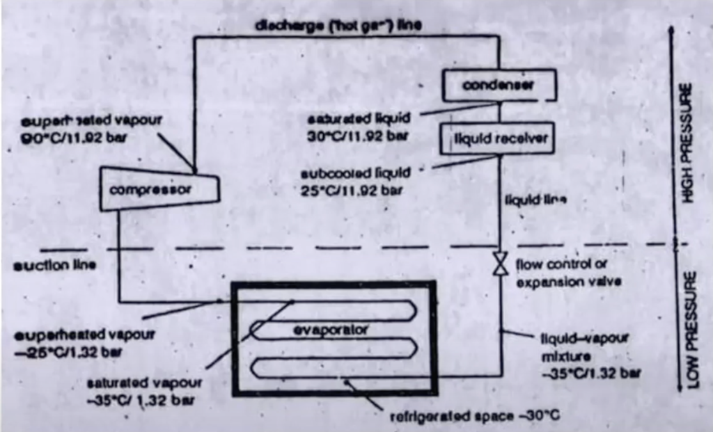
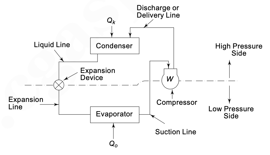
Refrigeration system that works on Vapour Compression Cycle has following basic components
- Compressor
- Condenser
- Expansion Valve
- Evaporator
- Refrigerant Fluid
We know that the saturation temperature (the temperature at which fluid boils or condenses) of a fluid varies with the pressure.
The compressor raises the pressure of vaporized refrigerant which in turn increases the saturation temperature. It also helps the refrigerant pump around the system. Now the refrigerant is in the state of Super Heat with High-Pressure vapor with high temperature (90 °C with 11.92 bar) goes to the condenser.
In the condenser, The refrigerant is sub-cooled, by circulating seawater (or air), to a temperature below its saturation temperature. In this, the refrigerant liberates heat to the seawater and vapor will get condensed to liquid with a decrease in the temperature. Now the refrigerant is in the state of Subcooled liquid i.e Low temperature and High pressure (25 °C with 11.92 bar) and goes to the expansion valve.
The expansion valve is the throttling device through which refrigerant flows from the high-pressure side to the low-pressure side. Due to pressure drop boiling point of the refrigerant comes down and it starts evaporating. The latent heat comes from itself and its temperature drops. ( to about -35 °C and 1.2 bar)
The refrigerant then enters the evaporator coil, where the cooling phenomenon takes place ( Eg. Fish room, meat room, etc). This refrigerant has a temperature lower than that of the surrounding temperature.
This cycle is know as Vapor Compression cycle and is repeated again and again.
Analyzing the PV Diagram for Refrigeration Cycle
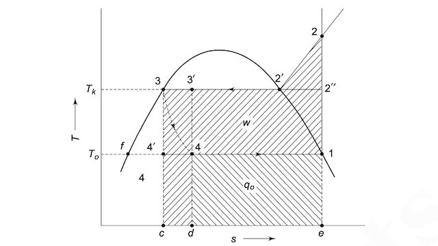
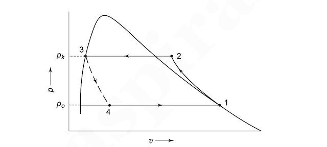
To fully understand the thermodynamics of a marine refrigeration plant, engineers analyze the pressure-volume (P-V) and pressure-enthalpy (P-h) diagrams. Below is a detailed breakdown of the four primary processes in the vapor compression refrigeration cycle as shown on a typical PV diagram for refrigeration cycle:
-
Process 1-2: Isentropic Compression (in the Compressor) The refrigerant enters the compressor as a low-pressure saturated vapor (or slightly superheated vapor). The compressor performs work on the working fluid, raising its pressure and temperature. On the PV diagram, this is represented by a curve sloping upwards and to the left, as the volume decreases while pressure increases. The refrigerant leaves the compressor as a high-pressure, high-temperature superheated vapor.
-
Process 2-3: Constant Pressure Heat Rejection (in the Condenser) The high-pressure superheated vapor enters the condenser, which acts as a heat exchanger. Here, it rejects heat to the circulating seawater (or air in domestic air conditioners). The refrigerant cools down to its saturation temperature, condenses at a constant pressure, and is subcooled. On the P-V diagram, this constant pressure process is represented by a horizontal line. At the exit, the refrigerant becomes a high pressure liquid, specifically a saturated liquid or subcooled liquid.
-
Process 3-4: Throttling / Expansion (in the Throttling Valve) The high pressure liquid flows through the expansion valve (or throttling valve), which is an isenthalpic expansion device. During this process, no heat is exchanged, and no work is done. The pressure drops significantly, causing a portion of the liquid refrigerant to flash into vapor. The temperature drops dramatically. On the P-V diagram, this expansion is depicted as a steep vertical or near-vertical drop in pressure with an increase in specific volume.
-
Process 4-1: Constant Pressure Heat Absorption (in the Evaporator) The cold mixture of liquid and vapor enters the evaporator coil. The refrigerant absorbs heat from the space being cooled (such as the meat room or vegetable room on a ship). As the refrigerant absorbs heat, it evaporates at a constant pressure and constant temperature. The liquid refrigerant undergoes a phase change until it becomes a saturated vapor at state 1, ready to be compressed again.
Discussion & Feedback
0Have a doubt, memory trick, or exam update? Share your insights with fellow mariners.